




Now What Should We Do? Looking Beyond the Pinpoint Test
When a pinpoint test leads to a replacement that doesn’t fix the problem, technicians need to look beyond the instructions.
October 15, 2026


When a pinpoint test leads to a replacement that doesn’t fix the problem, technicians need to look beyond the instructions.
Credit:
Government Fleet
8 min to read
“Replace with known good PCM, then re-test.” How many times have we, much to our dismay, reached this step in any kind of pinpoint test, or trouble tree, as they are sometimes referred to?
How many times have we followed this instruction, only to find out, much to our frustration, that the “known good PCM” that we just installed didn’t solve our diagnostic dilemma? How many times have we asked ourselves, “Now what should we do?”
I once heard an instructor of mine years ago state, “You know why they are called trouble trees? Because they get you into trouble!” Over the years I have had my fair share of “getting into trouble” situations by using a trouble tree/pinpoint test, either through my own fault or some kind of error in the trouble tree instructions.
Let’s discuss a few methods that can be used to minimize the chances of the above scenario occurring. Since I prefer to use the term “pinpoint test” (the word “trouble” has such a negative connotation for me!), let’s call them “Pinpoint Test Diagnostic Tips.”
Pinpoint Test Diagnostic Tips
Most pinpoint tests usually consist of an “Introductory Section,” where fault code description, wiring diagrams, and circuit descriptions of the components involved with the particular fault code that was retrieved are located.
Some even list the particular parameters required to set that particular fault code. Whenever you resort to actually using a pinpoint test, you should thoroughly understand this section before proceeding to the actual test section itself.
The main body of the pinpoint test contains the particular test steps for diagnosing a particular fault code. Most pinpoint tests have a header box at the beginning of each step that will give a description of what is actually being checked at that step.
An example of this would be the following: “Check Circuit XXX for a short to ground.” Immediately following this, in the same step, just below the header box, will be the test procedure(s) for checking to determine if “Circuit XXX” is shorted to ground.
It is very important to determine that the testing procedure shown is a valid method of checking for what is listed in the header. For instance, if the test instructions state to check the circuit with an ohmmeter, but also tell you to turn the key on before proceeding, you immediately know that this is incorrect.
It is then your responsibility to determine the proper means of testing that circuit. Blindly following any pinpoint test instruction without determining if the instructions are correct will definitely get you “into trouble.”
Opposite Code Inducement
Over the course of my career, I have lost count of the number of mistakes that I have found in pinpoint tests, which is why I try to avoid using them. So, you ask, what other diagnostic method should we use?
My preference? A thorough understanding of electricity and electronics, the correct definition of the fault code retrieved along with the parameters for setting that code, and the correct wiring diagram for the circuit(s) involved. My diagnostic method of choice is what I refer to as “OCI,” an acronym for “Opposite Code Inducement.”
Take a look at the wiring diagram shown below. This is a very, very oversimplified schematic representation of the circuits involved in most two wire sensor circuits. The small V inside the PCM represents the PCM internal voltmeter. In actuality, there is a lot more going on electronically inside the PCM than is actually depicted in the diagram.
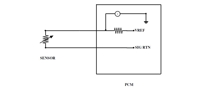
As represented by the electrical symbol in the diagram, the sensor in the circuit is a variable resistance sensor, for example, an engine coolant temperature sensor (ECT).
Credit:
Illustration by Mike Cleary
That said, for the purposes of diagnostics, it is all you really need to know in order to diagnose most fault codes that are hard faults, otherwise known as “on demand” codes (intermittent codes, often referred to as “memory” codes, are another discussion altogether).
The designation VREF represents the reference voltage circuit, and the designation SIG RTN represents the signal return circuit. As represented by the electrical symbol in the diagram, the sensor in the circuit is a variable resistance sensor, for example, an engine coolant temperature sensor (ECT).
Now, let’s put OCI to work. Suppose a fault code is retrieved for a high sensor input voltage. In this particular instance, the fault code definition would be “ECT voltage out of range high.” Although not shown in the illustration, for the purposes of discussion we will assume the reference voltage (designated as VREF in the diagram), is 5 volts.
By researching our reference information, we learn that for this particular vehicle and circuitry, the code setting criteria for a low voltage fault code is set when the PCM internal voltmeter senses less than 0.5 volts, and the code setting criteria for a high voltage fault code is 4.5 volts or greater.
Knowing what the parameters are for setting that code, for example, let’s consider the situation where we have retrieved an “Out-of-Range High” code, (that is, we know the PCM is receiving an input voltage in excess of 4.5 Volts).
What is our next step? First, we need to ask ourselves, “Is the PCM really receiving an out-of-range high input from the ECT sensor that is greater than 4.5 volts, or does the PCM just “think” (assigning human thought processes to a computer) that the input is out of range high? Is the internal PCM voltmeter really measuring greater than 4.5 volts at the point in the circuit where the internal voltmeter is tapped?”
What are the possibilities for that code to set? Think this through. Could be a bad sensor, or it could be a faulty PCM (either an internal voltmeter concern, circuitry issue, or a PCM processing issue).
It could also be a wiring problem outside the PCM, which in this case would need to be either excessive voltage drop (i.e. high resistance), or an open, in the VREF circuit between the PCM internal voltmeter and the sensor, or excessive voltage drop (again, high resistance), or an open in the SIG RTN circuit between the sensor and the PCM. Finally, it could be an issue with the PCM power supply circuit or ground circuit.
If you were using a pinpoint test, at some point it would probably tell you to connect a breakout box to take some voltage readings. Do we really want to hassle with that?
There has to be an easier way!
There is. Using the “Opposite Code Inducement” method we can come up with a quick and easy way of almost completely eliminating the use of a breakout box and pinpoint tests. So, getting back to the above example, again, we have a high voltage code.
Interpreting the Test Results
What can we do, as a technician, to induce the opposite code? We want to make the voltage at the internal voltmeter drop below 0.5 volts. (remember, we determined through our research that the low voltage code setting criteria was a voltage less than 0.5 volts).
How can we do this?
We cannot manipulate anything inside the PCM, so, in order to induce the opposite code for this example, we would merely unplug the sensor and connect a jumper wire between the VREF and SIG RTN circuits.
Then, go back with your scan tool and again run your code retrieval. If the code now retrieved has changed to the opposite code, what do we know? Or, in lieu of doing this, you could look at your scan tool pid data for the engine coolant temperature sensor and observe if it changed to the opposite extreme.
If it does, we have effectively verified our wiring circuits and our PCM internal voltmeter and PCM processing functions are operating normally, so we know that in this particular example, the sensor is the problem.
But what if the sensor isn’t the problem? What if we don’t retrieve the opposite code or pid data? Then we would simply plug the sensor back in, power up the circuits (turn Ignition “ON”), and with our digital multimeter back probe at the sensor connector to check for the correct voltage measurements on the VREF and SIG RTN circuits.
If we find circuit integrity on both circuits, we know we have a PCM issue. Finding the correct voltage measurements on both of these circuits also rules out a PCM power supply and ground circuit problem. If the correct measurements are not found, then it is a matter of voltage drop testing the circuits involved to determine the problem.
Conversely, if we originally retrieved a fault code for an input voltage that was out of range low, we could induce the opposite code by simply unplugging the sensor. This should make the measured voltage inside the PCM rise to greater than 4.5volts, and induce the opposite code.
If the code does in fact change to the opposite code, we know again, the sensor is at fault. However, if the code doesn’t change, we once again have wiring or PCM issues to consider.
In this particular instance, the types of wiring issues to consider are VREF shorted to ground, a wire to wire short between the VREF and SIG RTN circuits, or again, a PCM power supply or ground circuit issue. Again, if we verify the integrity of the circuits involved, the only item remaining to replace is the PCM.
Read and review this procedure a few times and let it sink in. It’s really quite simple when you give it some thought. Practice it on some “known good vehicles” so that you will be well acquainted with the procedure when the time comes to put it to practical use on a vehicle with a real problem.
It is important to mention at this point that the examples I have cited above are used solely for the purposes of explaining the diagnostic method of “Opposite Code Inducement” and may not apply to any one particular diagnostic scenario.
Make certain that the appropriate manufacturer’s service manual literature is consulted to make absolutely certain that all of the correct information is available for the particular repair scenario being addressed.
In a future column, I will discuss using OCI to diagnose fault code situations on three wire sensor circuits.
Now You’re Dangerous!
Subscribe to Our Newsletter
More Blog Posts

The Missing Link in Fleet Safety: Turning Data into Behaviour Change
Every municipal vehicle tells residents something about how their fleet is being managed. For King Township, Ontario, that visibility made speeding more than a driver performance issue.
Read More →
Flavor of the Decade: The End
As automakers pivot toward hybrids and extended-range models, the costly slowdown in battery-electric vehicle adoption raises questions about what comes next for the Big Three and government fleets.
Read More →
Why Technician Development Is a Retention Strategy
Clear development opportunities can help fleets show technicians how their skills and careers may progress within the organization.
Read More →
Building a Cross-Department Fleet Data Standard: What to Agree on First
As municipalities expand their use of fleet technology, the challenge is less about collecting data and more about making that data usable.
Read More →
7 Tips for Smarter Fleet Management
The potential to manage your fleet effectively while ensuring the safety of both employees and the community can often go untapped, but there are certain habits you can adopt to get to that point.
Read More →
Why Now Is the Time to Return to Government Fleet Expo
For fleet professionals who haven't attended GFX in a while, this year's event provides more than just education sessions and networking opportunities. From emerging leaders and innovative fleet strategies to industry recognition and peer-to-peer discussions, GFX 2026 reflects the changing landscape of public fleet operations.
Read More →
What to Expect at GFX
The Government Fleet Expo & Conference can be overwhelming in the best way possible. Whether you’re a first-time attendee or a returning fleet professional, these practical tips will help you plan ahead, stay energized, maximize networking opportunities, and make the most of every moment at GFX 2026 in Long Beach.
Read More →
How to Get the Most From an Industry Conference
A new strategy in how to present conference attendance justification for you and even for your staff and how you and they can benefit and even thrive in the conference environment.
Read More →
How Electric Vehicles as a Service Could Reshape Public Fleets
How the EV model can address concerns about meeting state mandates, cost, emissions and range anxiety.
Read More →
14 Metrics Government Fleets Should Track
The metrics government fleets should track to get a full understanding of their fleet operation.
Read More →